

Working Principle of Schorch Power Unit
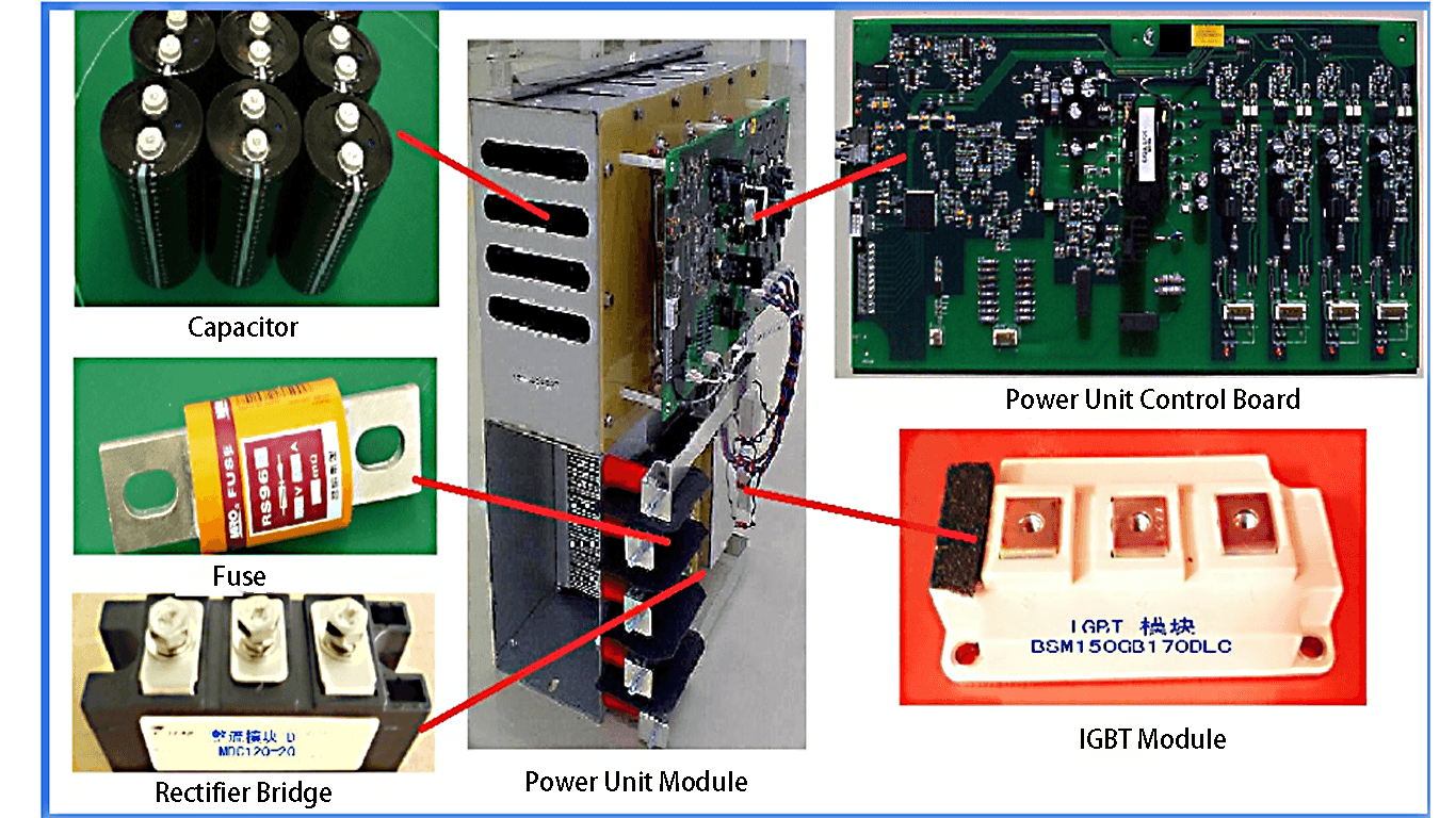
The basic topology of the Schorch series frequency conversion power unit is an AC-DC-AC three-phase rectifier/single-phase inverter circuit.

The three-phase AC input signal is rectified into pulsating DC by a three-phase uncontrollable bridge rectifier circuit, and then filtered into DC voltage by a filter capacitor and sent to a single-phase bridge inverter circuit, which is composed of four IGBTs, forming an H-bridge structure. By properly controlling the switching sequence of the four IGBTs, the output of each unit can get 0V, ±Ud3 voltage levels (Ud is the amplitude of the DC voltage of the power unit). The 8 power units of each phase of the VFD (10KV system) are connected in series (the output u1 of unit A1 is connected to the output u2 of unit A2, and so on, and finally the outputs u1 of three units of A8, B8 and C8 are connected together as the midpoint of the converter), and 17 voltage levels can be obtained at the output of each phase.

The DC bus voltage is about 960V when the rated voltage of the power unit is 690V. The inverter consists of two IGBT modules with 1700V voltage withstand to form an H-bridge single-phase inverter circuit, which is controlled by PWM to obtain a high-voltage frequency conversion AC output at both ends of u1 and u2, with an output voltage of 0-690V for single-phase AC.
The inverter output adopts multi-level phase-shift PWM control technology. The power units of the same phase output the fundamental voltage with same amplitude and phase, but the carrier waves of each unit in series are staggered by a certain electrical angle to achieve multi-level PWM, and the output voltage is very close to the sine wave. Each level step is only the size of the unit DC bus voltage, du/dt is very small, so that the motor insulation will not be affected.
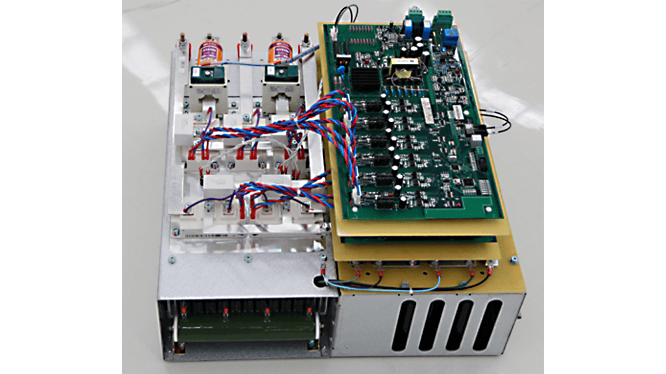
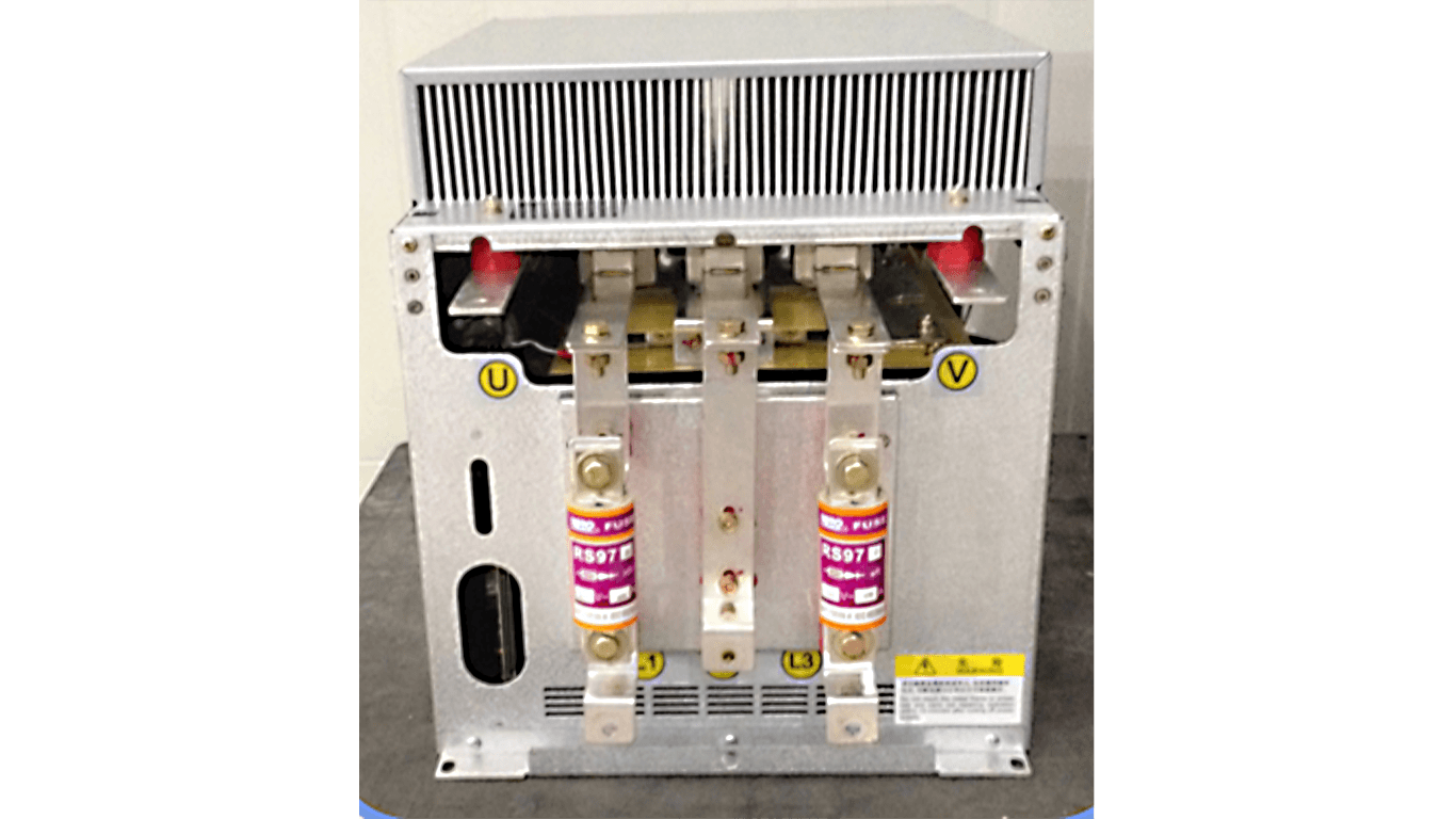
The communication between the power unit and the main control system is carried out through optical fiber to solve the problem of isolation and interference between strong and weak power. Power unit adopts modular structure, all power units can be interchangeable, and maintenance is also more convenient.
The power unit adopts a lower switching frequency to reduce the switching loss, and can be used without surge absorption circuit to improve the power of the VFD. Due to the adoption of multi-level phase-shift PWM, the equivalent output switching frequency is high and the number of output levels increases, which can greatly improve the output waveform and reduce the output harmonics, and the motor heating, noise and torque pulsation caused by harmonics are greatly reduced. So the Schorch VFD has no special requirements for motor, it can be used for common HV motor, also can be used for old motor without derating.

Stay connected
Be the first to know about our new product launches, latest blog posts and more. The production base of Schorch Electric Co., Ltd. is located in Suining City, Sichuan Province. It adopts the advanced technologies and manufacturing techniques of Europe. The production technologies are advanced, stable and reliable.
Any question or request?
Click below, we’ll be happy to assist. Contact us